(Revised: 5 September 1998)
http://www.luizmonteiro.com/Learning_VOR_Sim.htm
The FAA has placed many VOR (VHF Omni-directional Range) radio stations around the United States. (VHF=108 to 117.95 MHz for VORs.) VOR receivers in airplanes can detect at which radial, given as an angle between 0 and 359 degrees from the magnetic-north-pole great circle direction, of a selected VOR from which the aircraft is located, either as a "to" radial or a "from" radial. The radials are measured from the magnetic north, so the navigator has to correct the reading by adding or subtracting the magnetic pole variation from the geographic pole direction, since FAA navigational charts and latitude/longitude values are based on the latter. Of course, the VOR circles on the charts are plotted with the magnetic pole direction as 0°. VOR radial angles have errors of about 1 or 2 degrees.
If one is going to an airport near a VOR station, and many stations are located near airports, one can simply head the craft in the direction of the reported "to" radial of the relevant VOR. If one is traveling away from an airport near a VOR station, one can observe the required radial to lead to the destination and head the craft in the direction of the reported "from" radial of the relevant VOR.
Flying is not always so simple, however. Foremost is the fact that VHF signals bend very little as they travel, so the distance that a VOR signal can be received is quite limited, of the order of 50 to 100 nm (nautical mile=1852 meters) depending on the terrain and the aircraft altitude. So for a trip of over 100 nm one must use more than one VOR.
Also, when one flies between airports which do not have nearby VORs, one must use off-course-axis VORs. Then one needs two VORs in about each 50 nm section of the trip in order to find a craft's position in two-dimensional space. VORs are not always that readily available.
So a navigator does the best job possible in locating pairs of VORs that are receivable along the course of the proposed flight. This can be laborious because it is often difficult to read the radial notations on the navigation charts, particularly in congested areas. Also, often the VOR and the course points are on different charts. Then the "from" radials for the VOR pairs for various points along the flight are recorded to be referred to during the flight to aid the navigator in keeping the craft on course.
After laboriously recording VORs' radials for points on the courses of many flights, I devised a graphical method to record and use the VORs' radials without having to read VOR radials off of charts.
All one needs are the longitude and latitude values for the origin and destination airports, and the longitude/latitude and magnetic variation values for the VORs to be used. The longitude/latitude values can be obtained from various manuals of airport data (e.g., Flight Guide, Airguide Pub., Inc., 1207 Pine Ave, P.O. Box 1288, Long Beach CA 90801). The magnetic variations can be read easily off of FAA navigation charts. (I have suggested to Flight Guide that VOR magnetic variations be published for VORs in future issues.)
This method enables one to follow a graph of one VOR radial versus the second VOR radial as one flies, which is easier than looking at a table of numbers. It is a much easier way to get the VOR radials than reading them off of a navigation chart.
In order to plot one VOR radial versus the second VOR radial, one must calculate the VORs' radials for equal intervals of positions of the aircraft as it flies on a straight course from origin to destination. There are some subtle difficulties in doing this calculation:
I use the spreadsheet program Quattro Pro for Windows, Version 6.0 to do the calculations. Here is the calculation procedure that I used:
Note that all the user needs to do is obtain the data described in 3. and 4. and 11. above, put the data into the spreadsheet and print out the three plots.
Consider a proposed flight from Blacksburg, Virginia (BCB) to Hot Springs, Virginia (HSP). (At elevation 3792', HSP is the highest public airports east of the Mississippi River in the United States; and an exciting landing it provides on runway 24, which sits at the top of a steep and high cliff.) This is a flight of 52 nm, so one could possibly get by with only one pair of VORs. However, the available VOR pairs are near the beginning and the end of the course. So one needs two pairs of VORs for the flight. I use FliteStar (MentorPlus Software, 22781 Airport Rd. NE, P.O. Box 356, Aurora OR 97002) to plan such flights. Here is the map for this flight as created by FliteStar:
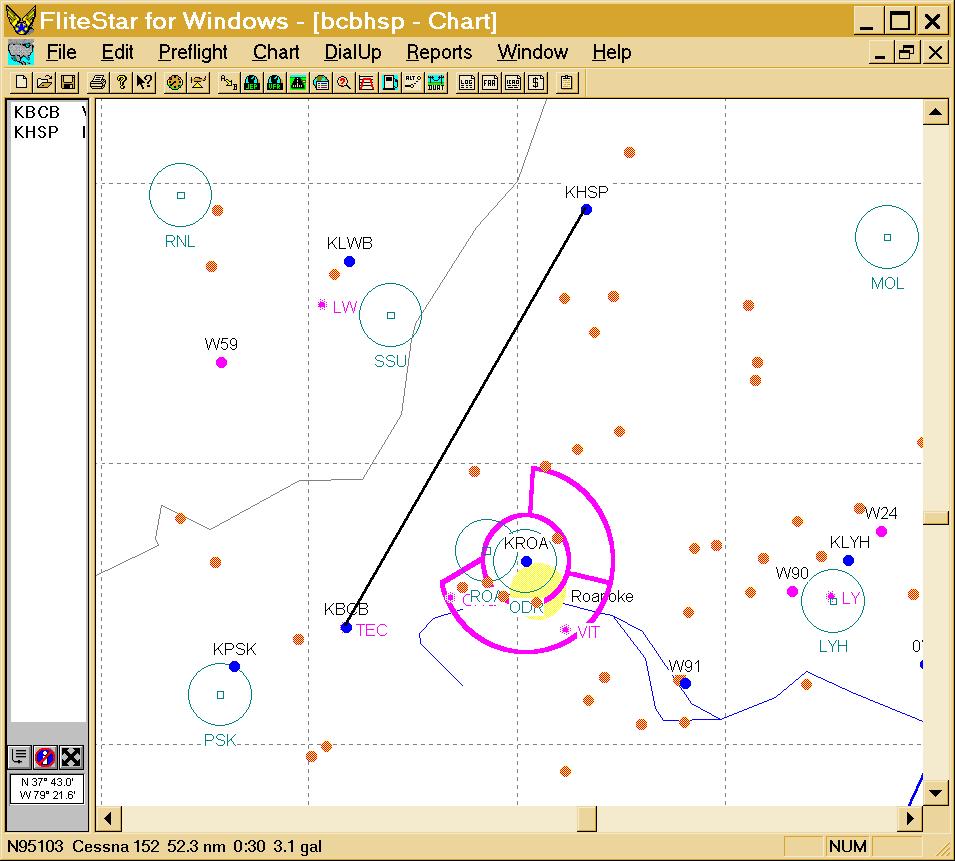
The VORs are indicated by circles. One could choose VOR pairs (PSK, ROA), (ROA, SUU) or (SUU, MOL). I propose the pairs (PSK, ROA) and (SSU, MOL). (Note that I choose the VOR to the left of the course as VOR 1 and the one to the right at VOR 2. For some courses it will not be possible to use VORs on opposite sides of the course; then I would choose the closest one as VOR 1.)
See below for information about how to get the Quattro Pro for Windows spreadsheet used for this calculation.
I have checked these calculations (and many other calculations) with radials I obtained from FAA navigation charts and they are within 1° to 3°, which is of the order of the VOR system's accuracy and the accuracy with which one can read navigation charts.
The plot of VOR-2 (ROA) angles versus VOR-1 (PSK) angles is:
Note that the VOR-2 angle goes through 359° and then becomes 0° about half way from BCB to HSP. The VORs are most helpful when the slope of the curve is largest, which is early in the course. One can use this graph while flying as follows:
The plot of VOR-1 angles versus course distance is:
The plot of VOR-2 angles versus course distance is:
The VOR angles to the distance of closest approach (perpendicular line to the course line) to the VOR can be used to move to that VOR when lost. Note that the VOR-1 angles for the course do not intersect the VOR angle of closest approach; i.e., the perpendicular to the course line lies beyond an end of the course, in this case before the course beginning.
I take all three of these plots for each VOR pair with me when I fly.
A similar spreadsheet page can be created for the second pair of VORS (SSU, MOL). The plot of VOR-2 (MOL) angles versus VOR-1 (SSU) angles is:
One could use this VOR pair for the entire course if reception were available over the entire course, which it is not early in the course.
The plot of VOR-1 angles versus course distance is:
In this case the VOR angles for the course do intersect the VOR angle of closest approach.
The plot of VOR-2 angles versus course distance is:
In this case the VOR angles for the course do not intersect the VOR angle of closest approach; the VOR perpendicular is beyond the destination airport.
These six curves can be printed out at full-page size and referred to as one flies the course.
The Quattro Pro for Windows (Ver. 6.0) spreadsheet for the VOR angles
calculation described herein is available on the Internet in Zipped form:
http://www.roperld.com/aviation/vornav.zip
The Excel 97 spreadsheet for the VOR angles calculation described herein
is available for downloading:
http://www.roperld.com/aviation/vornav.xls
Other spreadsheet programs may be able to convert these file to their formats.
I have heard that the VOR stations will eventually disappear as GPS navigation becomes more prevalent. However, there are some good reasons for this not to happen.
It is well known that communications satellites in high earth orbits, which is the case for GPS satellites, are susceptible to damage by radiation from intense solar activity or by collisions with space debris.
Recently my GPS quit working while I was in some unexpected bad weather during a flight. I managed to get the GPS working again, but it felt good that I had the VOR system as a backup.
The author assumes no responsibility for any consequences of the use of the material contained in this document.