L. David Roper
http://arts.bev.net/RoperLDavid/
30 October, 2009
If you know little about solar greenhouses (SGH), see Solar Greenhouses.
The purpose of this web page is to give explicit instructions for building a solar greenhouse (SGH) with the Subterranean Heating and Cooling System (SHCS) similar to the one the author designed and helped build for the YMCA at Virginia Tech.
Architectural Design
Building Location
Underground Walls
Building the Wooden Structure
Polycarbonate on South Roof
Finishing the Outside
Cistern
Building the Heat Sink
Finishing the Inside
Electrical Work
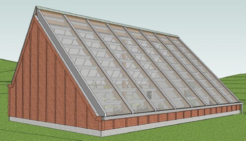
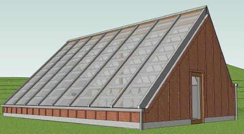
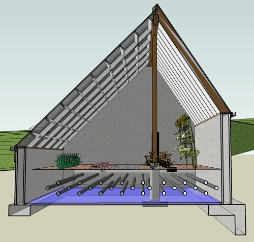
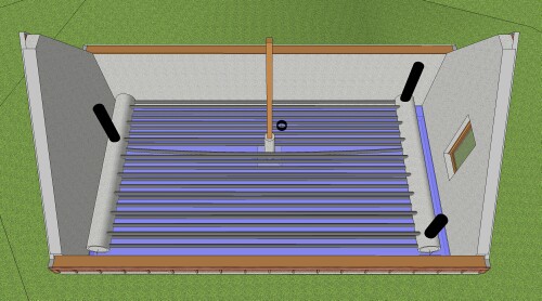
You will need detailed architectural drawings. The firm of Colley Architects PC in Blacksburg VA can provide appropriate drawings for the size of SGH utilizing the SHCS that you want to build. Here are some of the views created by the computer model made by Colley Architects for the YMCA at VT:
|
|
|
|
The south side of a solar greenhouse must not be in the shadow of trees or buildings during the fall, winter and spring months. (It will probably be shut down during summer months; shade would be beneficial then.) Evergreen trees on the north would be ok, but then you need to do more filtering of the water off the roof before it goes into the cistern. The Solar Pathfinder is a useful device for predicting shadows at a location for different times of the year.
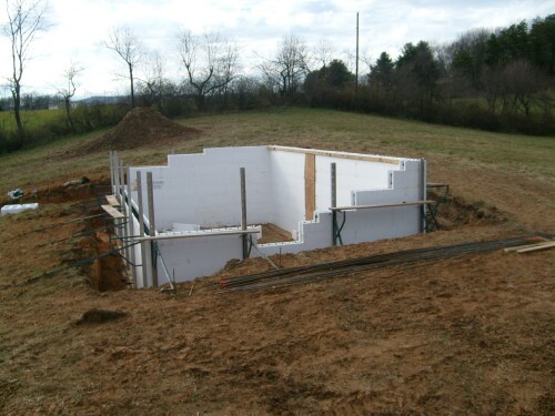
The best location is near the top of a moderately-sloping hill that faces geographical south. For example, the YMCA at VT solar greenhouse:
 Note the footer for the center peak post |
 |
The footer in the back has a special structure:
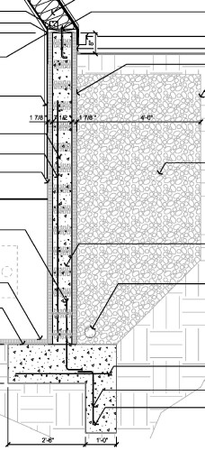
The inverted L shape is to hold the back wall vertical. Note the #57 stone behind the back wall. An architect, with the help of a structural engineer, needs to draw up the specifications for this.
The deviation of the glazed roof direction from geographical south should not be more than a few degrees. The purpose of the hill is to make it easy to berm the north side of the building. (Berm: "a bank of earth placed against an exterior wall or walls of a house or other building as protection against extremes of temperature") Note that the bottom of the north insulated roof is about four feet higher than the bottom of the south glazed roof, which four feet is to be bermed.
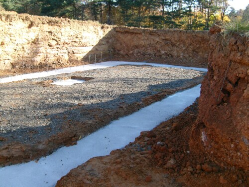
The walls that are underground need to be well heat-insulated and impervious to external ground water. We used Reward Walls ICF (Insulated Concrete Forms) as shown in the picture above and the pictures below. You could use standard wood-formed concrete or precast concrete walls with insulation installed on both sides, which may be less expensive than ICF. If you use ICF, have someone with experience building with ICF help you.
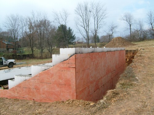
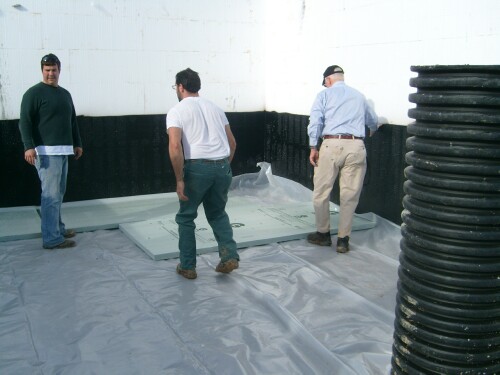
Ground water must not be allowed to enter the SGH. Both sides of the insulated concrete walls need to be water proofed:
 |
 |
The black material is on both sides. The outside also has "drainage panels" on top of the black material. The black material was later extended higher inside up to the bottom of the door. It is the Tuff-N-Dri water proofing system.
Of course, there are 4" perforated drain pipes covered with #57 rocks around the perimeter of the building at the footer level, taking ground water down the hill from the building.
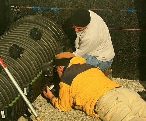
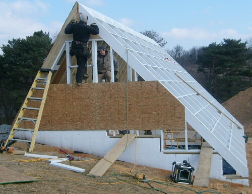
A long fork lift is needed to hold the peak beam in place while the rafters are installed:
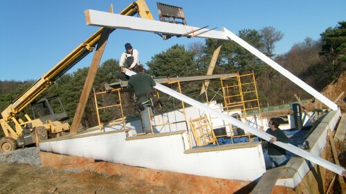 |
 |
 Note the 2"x6" boards that connect the south rafters 2' apart, to help support the polycarbonate sheets. Note the 2"x6" boards that connect the south rafters 2' apart, to help support the polycarbonate sheets. |
 |
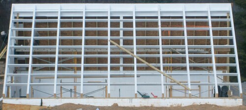
The polycarbonate comes in whatever length needed. The YMCA SGH ones are 20' long:
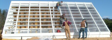 |
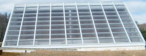 |
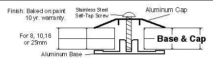
The polycarbonate sheets are attached to the rafters using the Base and Cap system:
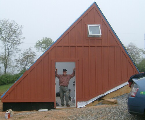
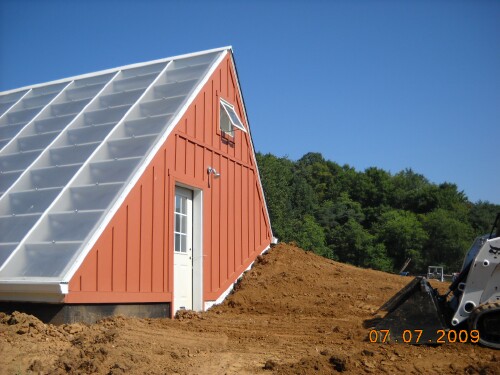
Hardie board is used on both the outside and the inside, because it resists moisture and insects. Batten boards are used on the outside for weather-proofing and aesthetic reasons:
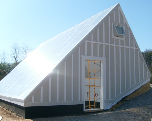
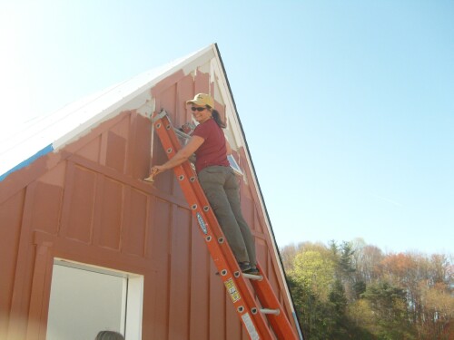
It is easiest to paint the Hardie board before it is installed. Here the batten boards were painted with primer before installation.
It is painted barn red:
 |
 |
For details about the vent windows and their automatic openers, see http://www.roperld.com/science/ymcasolargreenhouse.htm#vent. If I were installing vent windows again I would make them twice as big to allow for more cool air to be pulled into the SGH in hot weather.
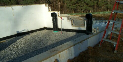
A 2000-gallons concrete septic tank is used as a cistern placed downhill from the SGH:
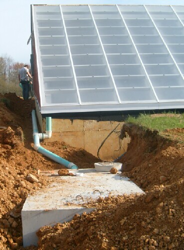
If any deciduous trees are within wind distance, filter the leaves out before rain water from the roof enters the cistern.
A sump pump is needed to pump the cistern water into a pressure tank in the SGH. Install the sump pump at least 6" off of the floor to minimize pumping gunk that collects on the bottom.
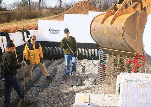
The heat sink has the following components from the bottom up:
Contrary to what we did, I recommend that the structure be built before the heat sink is built, to protect the heat sink from inclement weather! To allow using a large mechanical shovel to put the #57 rocks in, the ends of the building should be left open until the heat sink is built.
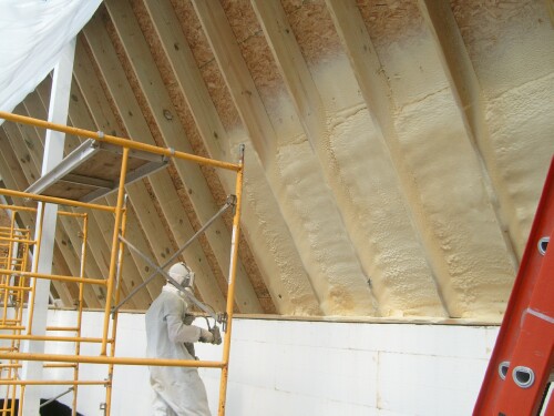
Closed-cell foam insulation needs to be blown between the north-roof rafters and the two ends' studs for 3" or more thickness:
 |
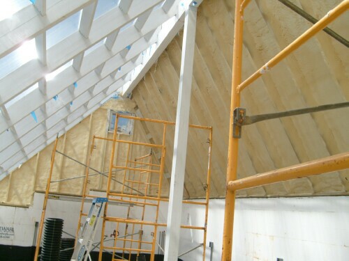 |
Hardie board was also used for the roof and end walls on the inside:
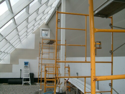 |
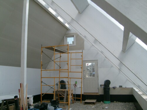 |
It is easiest to paint the Hardie board before it is installed. Here some was but most wasn't. An extension rod was used to paint the inside of the roof using rollers standing on the floor. Scaffolding is needed to finish painting the peak and the tops of the two ends.
The walkway is 16" of #57 rock separated from the soil by Hardie board with Trex or ChoiceDek composite boards on 2" ribs every 2' under them on top of the rocks.
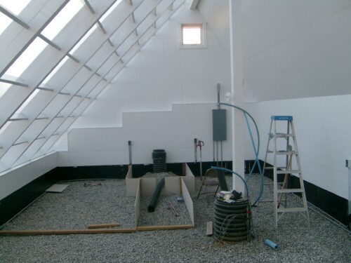 |
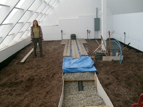 |
Note that an extra slotted pipe is inserted in the middle of the walkway rocks for extra heat/water storage.
2"x4" posts were embedded in the rocks where two Hardie boards meet and 2"x4" boards were used as horizontal supports about every 6' along the Hardie board, held by screws to the Hardie-board sides. It is best to install the soil at the same time as the rocks are installed to reduce the pressure of the rocks on the Hardie-board walkway sides.
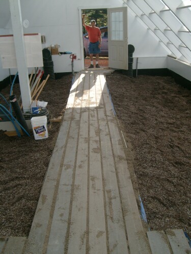 The door was incorrectly placed (not at center as it should have been), so the path had to jog near the door. |
Shelves at the west end hold the inlet pipe in place and provide storage: 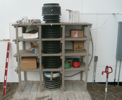 The white item just below the bottom shelf is the heat-sink fan. |
If I were building the walkway again I would build a rigid frame out of 2"x4"s and then put the Hardie boards on the inside of the frame to make a more rigid walkway. Then the soil could be added after the SGH structure is totally finished. I would mix the soil (SunGro and compost) outside the SGH and then move it in, to cut down on dust in the SGH.
Hardie board was used to create a form for a pad for the water-pressure tank:
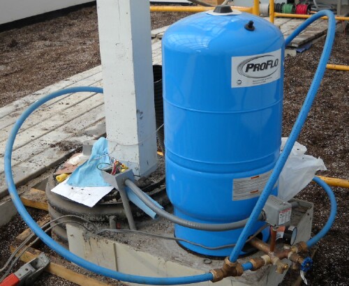
The pad contains about 12" of #57 rocks (on top of the 3' of heat-sink rocks) underneath about 4" of concrete.
If construction occurs during warm weather, it is best to do the electrical work immediately after the structure is built and enclosed to keep the temperature from becoming very high inside. At least the vent exhaust fan in the west vent window should be connected early. We did not do that, and had a temperature of nearly 150 degrees on some days in May 2009.
Thermostatically-controlled electric openers for the two vent windows were installed:
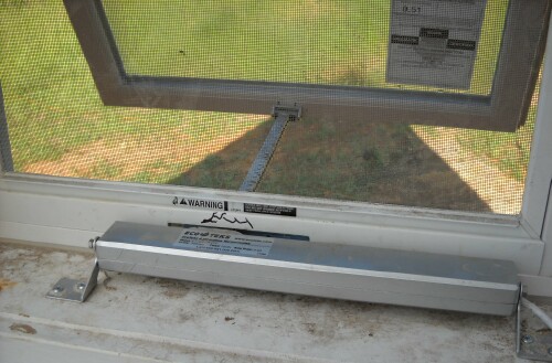
A thermostatically-controlled fan was installed in the west vent window. I suggest removing the direction and speed control of this fan and put it in the electrical-control box, so that it can be easily controlled.
Here is the electrical-controls box:
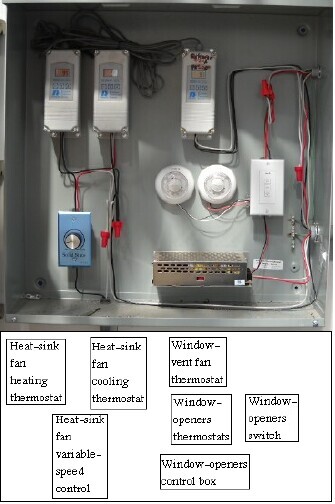
There is a front cover to the control box, which is swung out a few inches at the bottom to let greenhouse air in. However, the air inside the control box might still be different than the air in the greenhouse. The 3 main thermostats at the top left in the control box have probes on long wires, so the 3 probes are placed outside the control box. That leaves only the 2 circular window-opening("hot")/closing("cold") thermostats’ temperature sensors inside the control box. So, the 2 window-opening/closing thermostats are set at 75 degrees to open and 55 degrees to close. The vent-window-fan thermostat is set at 85 degrees to turn on and 65 degrees to turn off. Thus, up to a 10-degree difference between the air inside the control box and the greenhouse air will be ok.
The blue switch/rheostat on the lower left turns the heat-sink fan on/off and varies the fan speed. The white switch on the right manually opens (top button) and closes the vent window (bottom button); it only works when the "hot" circular window-opening thermostat is set to its maximum temperature and "cold" circular window-opening thermostat is se to its minimum temperature.
For many important details about the electrical work, see http://www.roperld.com/science/ymcasolargreenhouse.htm#electric.
For details about instrumentation, see http://www.roperld.com/science/YMCAsolargreenhouse.htm#instruments.
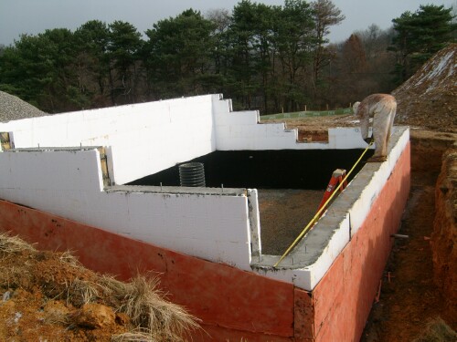
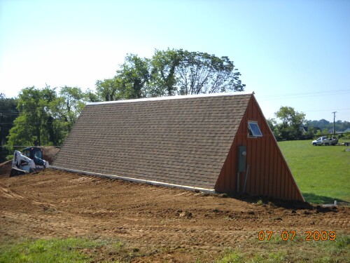
Some of the dirt excavated was used to berm to the top of the ICF walls:
 |
 |
 (
(