Physics of the 2005 Toyota Prius
The 2004/2005 model of the Toyota Prius automobile is a parallel/series
full hybrid without a standard transmission. Instead, a small set of planetary
gears, called a "Power Split Device" (PSD) serves as the mechanism for driving
the wheels of the vehicle in a manner that simulates a continuously variable
transmission. Complex electronic controls manage the PDS, so it is called an
Electronic Continuously Variable Transmission (ECVT).
|
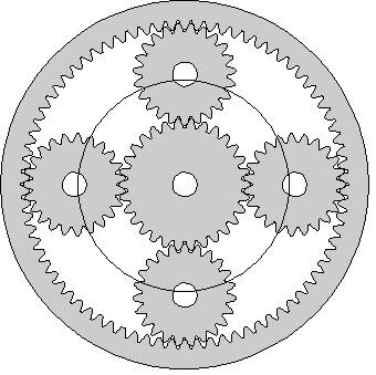
This is the arrangement of the Power Split Device
gears.
(Taken from
The
Power Split Device by Graham Davies.) |
The
diameter is about the height of a soft-drink can. |
| The outer gear with 78 inward teeth is called the
"Ring" gear. The center gear with 30 teeth is called the
"Sun" gear. The four middle "Planet" gears' shafts are attached
to a circular "Planet Carrier" that can rotate around the same axis as
the Sun gear. The number of teeth in the planet gears is not important. The
ring gear also has teeth on the outside which drive a steel chain that leads to
reduction gears and the front-axle differential. |
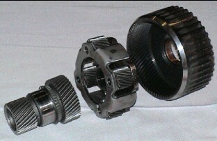
As shown in the diagram below the Planet Carrier is attached to the
gasoline engine shaft, the Sun gear is attached to the smaller electric
generator/motor (SGM = MG1) and the Ring gear is attached to the larger
electric motor/generator (LMG = MG2) and the vehicle's wheels through some
reduction gears and a standard differential.
(Taken from
PowertTrain
Components by Graham Davies.) |
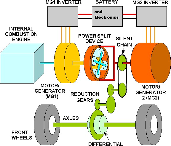 |
| A drawing of how the engine and motors system is
laid out (from
http://www.ornl.gov/~webworks/cppr/y2001/rpt/122586.pdf): |
 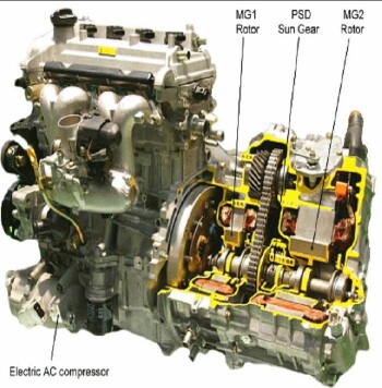
"Generator" refers to the smaller
generator/motor (MG1 = SGM); "Motor" refers to the larger motor/generator (MG2
= LMG). |
Toyota Prius Specifications
- Engine: 1.497 cc, 76 hp (57 kW) @ 5000 rpm, compression ratio
13.0/1, Atkinson cycle
- Motor/generator: 500 V Permanent Magnet rotor AC Sync, 67 hp
(50 kW) @ 1200-1540 rpm
- Generator/motor: 500 V PM AC Sync, 17 hp (13 kW). Starts engine
at 1000 rpm when needed. Can turn up to 10,000 rpm.
- Traction Battery: 201.6 V Ni-MH, 21 kW (28 hp)
- Net Hybrid System power: 110 hp (82 kW)
- Heated coolant before starting engine
- Regenerative coasting and braking
- Realistic Mileage: 40-50 mpg (EPA: 51-60 not so)
- 90% less emmisions than other new cars.
|
|
Many more details about the mechanics and electronics of the 2005
Prius are available at:
The first of the above links gives a graph of power measurments
for different vehicle speeds: |
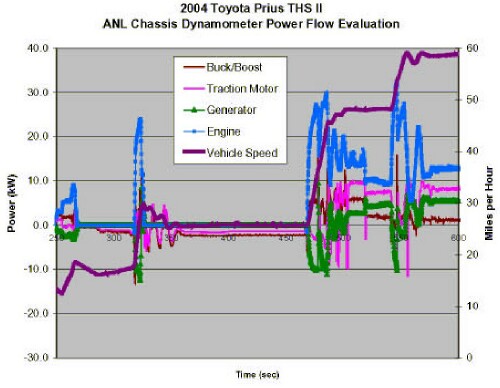
Buck/Boost = power from the 201 volt battery being
boosted to 500 V to run LMG or bucked from 500 V to 201 V (negative power) to
charge the battery. Note how it closely matches the LMG power. Traction Motor =
LMG. Generator = SGM. Vehicle speed is given on the right scale. |
- Starting from the left, the speed is about 12 mph and the
generator (negative power for SGM) starts the engine.
- The car accelerates to about 19 mph and then deccelerates a
little; then the engine turns off. The LMG turns into a generator to charge the
battery.
- Then the car accelerates to about 30 mph. The SGM starts the
engine again and a large peak of engine power does most of the work, with help
from LMG. Note that LMG oscillates between providing motive power and charging
the battery (negative power) after the acceleration.
- The car speed slows to about 26 mph with the engine off and
the LMG charging the battery slightly.
- Then the car accelerates to about 48 mph. The engine is started
by SGM and provides the power for the acceleration. Note the power oscillation
for LGM again and a complementary oscillation of the engine power. The SMG also
oscillates between being a generator to send power to LGM or charge the battery
and being a motor to power the wheels.
- At the steady speed of about 48 mph the engine provides about
10 kW, the LMG provides about 8 kW and the SGM provides about 4 kW to power the
motion of the car.
- Then the car accelerates again to about 59 mph. SGM becomes a
generator to provide power to LMG, which shows a short burst of power. Again
oscillations occur.
- Finally, at a steady speed of about 59 mph the engine power is
about 12 kW, the LMG power is about 9 kW and the SGM power as a motor is about
5 kW. The battery (Buck/Boost) power is about 1 kW, so the
|
Measurements made in France
regarding the power situation for SGM and LMG:
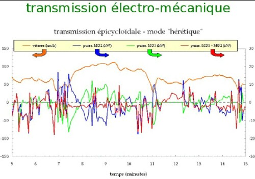 |
| Note that SGM=MG1 and LMG=MG2 alternate between being
motors and generators, with a net generation to charge the battery. (Vitesse =
speed, Puiss. = power) |
Graham
Davies has determined many of the mechanic parameters and operating
procedures of the 2004/2005 Toyota Prius' power train. The following table
lists some of the important facts that are necessary to study the physics of
the operation of the Pruis.
|
Let:
- S = angular velocity (rpm)
of the Sun (inner) gear that connects to the Smaller electric generator/motor (SGM = MG1) It is a
generator providing power to the larger motor/generator or to the battery,
except when it is needed as a motor to start the gasoline engine. Sometimes it
acts as a motor to power the wheels.
- L = angular velocity (rpm)
of the Ring (outer) gear that connects to the Larger electric motor/generator (LMG = MG2) and to
the reduction gears to the vehicle's wheels. It is configured as a motor when
it is need to provide motive power and is configured as a generator when it is
needed to charge the battery.
- E = angular velocity (rpm)
of the Planet Carrier, and thus the Engine
shaft.
- V = speed (mph) of the
vehicle. Davies calculated that L = 59.2*V for the 2001-3 Prius; however for
the 2004-2005 Prius it is L = 60.1 V .
|
Davies showed that the equation that connects these variables
is:
S = (1 + 78/30) E - (78/30) L = (1 + 78/30) E -
(78/30) 60.1 Vand that the engine torque (Et) passed to the
sun gear is St = [30/(30+78)] Et and the
engine torque passed to the ring gear is Lt =
[78/(30+78)] Et.
Another way to think of the PSD is as an
asymmetrical differential. For a differential the number of teeth is the
same for the two sides of the differential that feed power to the two
wheels.
Then the equation is S = (1 + n/n) R - (n/n) L = 2 R - L or 2 R = S
+ L, where n = number of teeth in both gears. The Pruis has such a standard
differential located below the engine-motors complex. |
|
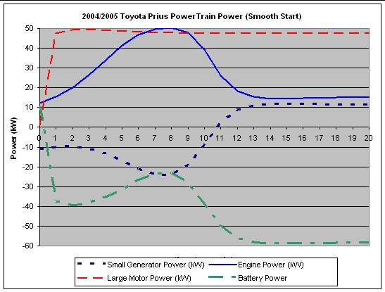
An arbitrary example that probably does not
fit the system power parameters, but may be a reasonable first
approximation:
- Let V = 60 tanh(t/5); i.e.,
the speed of the vehicle smoothly goes from 0 at 0 seconds to 60 mph at 10
seconds.
- Let E = 500 + 6000[1 +
tanh({t-5}/5)]/2 - 5000[1 + tanh({t-10}/2)]/2; i.e., the engine rpm
smoothly goes from about 1200 rpm to about 4500 rpm and then settles down to
about 1500 rpm.
|
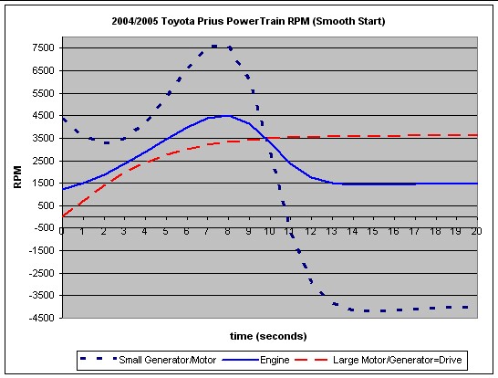 |
| Note that the SGM has to speed up in order that the engine can have
a high rpm and that the vehicle can smoothly approach the final speed. In this
case the SGM is electronically configured as a generator and passes the power
it generates on to the LMG to supplement electric power from the battery. Both
the LMG and the engine provide the power needed to accelerate. At the final
speed, the LMG is electronically configured as a motor to supplement the power
of the engine or as a generator to charge the battery. At higher speeds the SGM
is electronically configured as a motor to help power the vehicle or as a
generator to feed power to LMG. The peak torque of the engine and the motor
occur around 4200 rpm and 0-1200 rpm, respectively, just at the right time to
cause the vehicle's acceleration. Some of the power the LMG uses for the
acceleration comes from the SGM. This model does not account for the
alternation between LMG and SGM as generators and motor, as shown in the actual measurements given above. |
| The following Power-Split-Device simulations are taken from
http://home.earthlink.net/~graham1/MyToyotaPrius/Understanding/WhatsGoingOnAsIDrive.htm: |
Moving in reverse:
 |
Starting engine at rest:
 |
Accelerating and hill climbing:
 |
Cruising:

|
Coasting, braking and slow driving (< 25 mph)
 |
All together:
Moving in reverse:
|
Starting engine at rest:
|
Accelerating and hill climbing:
|
Cruising:
|
Coasting, braking andslow driving (< 25
mph):
|
|
|
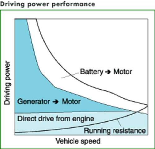
Taken from a Toyota document. |
Note:
- At very low speeds most of the power is supplied by the
LMG.
- If the engine is running most of the power for LMG comes from
SGM by means of the engine driving it.
- As speed increases the engine provides increasingly more of the
power.
- At medium speed the LMG and engine approximately equally share
in providing power to the vehicle.
- At high speed most of the power comes from the engine.
|
| Below is an attempt to mathematically model the
bahaviour of the Prius power system. To do so mathematical expressions are
needed for the engine and LMG power and torque: |
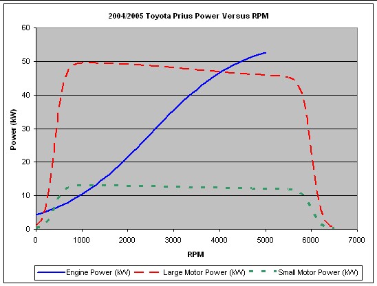
Engine power versus rpm:
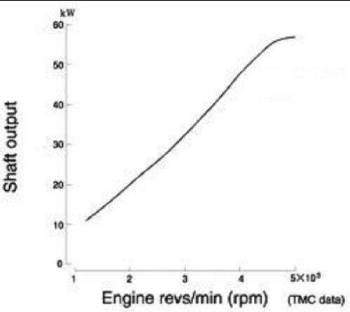 |
An equation that fits the above curve fairly well is
Ep = 57 [1 + tanh({rpm - 2500}/2000)]/2
.
See below for the fit. |
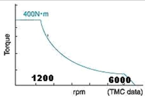
Engine torque versus rpm:
 |
An equation that fits the above curve fairly well is
Et = 109 tanh(rpm/1097) .
See below for
the fit |
Motor power versus rpm:
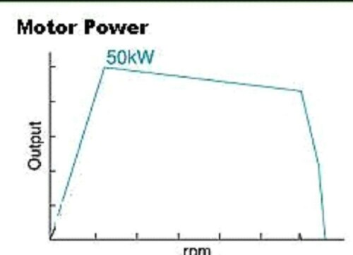 |
An equation that fits the above curve fairly well
is
Mp = 50 [1+tanh({rpm-600}/200)]/2-5
[1+tanh({rpm-3500}/2000)]/2-45 [1+tanh({rpm-6500}/100)]/2 .
See
below for the fit. |
Motor torque versus rpm:
 |
An exponential equation that fits the above curve
fairly well is
Mt = 85.39 + 10.38 exp[(rpm -
4369)/1137].
See below for the fit. |
The following curve shows the fits of the equations
given above to the engine and motor power curves:
 |
The following curve shows the fit of the equation
given above to the engine torque curve:
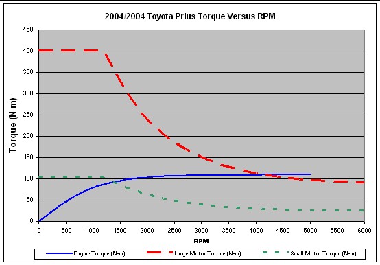 |
| When the LMG is being used as a motor, the engine p
ower curve given above can be used to calculate its contribution to the power
sent to the wheels. A similar curve is needed for the SGM when it is being used
as a motor; perhaps the same curve scaled down to the relative power of SGM is
applicable. When LMG or SGM are being used as generators, the power generated
by them is calculated by multiplying the torque supplied to them by their
rpm. |
Now we combine the example given
above with the engine and motor power curves and the SGM power calculated
by multiplying the appropriate fraction of the engine torque times the SGM
rpm:
Note that SGM is a generator (negative power) that supplies
power to the LMG, along with the battery. Once the rpms are high, the LMG
provides almost constant power. At some point these curves do not apply because
maintaining a constant speed does not require much power; so the motor becomes
a generator to charge the battery. In fact, as the measured
data given above shows, SGM and LMG alternate between being generators and
motors, with a net generation to charge the battery. |
Modes of Operation of E, S and L
The engine E can have the following modes of operation:
- All valves closed such that the engine crank shaft does not
turn.
- Valves opened to allow the engine to brake the motion (B motion
selector).
- Engine running.
The small generator/motor SGM or S can have the following modes of
operation:
- Freely turning with no connection to the electrical system.
- Operating as a generator, supplying power to LMG and/or the traction
battery.
- Operating as a motor to start the engine or provide power to the
wheels
The large motor/generator LMG or L can have the following mode of
operation:
- Freely turning with no connection to the electrical system.
- Operating as a generator, supplying power to SGM and/or the traction
battery.
- Operating as a motor to provide power to the wheels
Power On
When the driver pushes on the foot brake pedal and presses the finger
Power button, the vehicle's electrical systems are started, making the
accelerator foot pedal active.
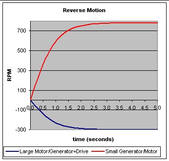
Reverse Motion
Assume that the first motion is to back out of a garage. The hand shift
lever is pushed left and up to engage the electric reverse-motion mode. The
driver has seven seconds to back the vehicle out of the garage before the
gasoline engine starts to warm up itself and the catalytic converter.
First consider what happens in the first seven seconds. The engine is
immobilized with all 12 valves in the 4 cylinders closed, so that air
compression in the cylinders prevents the engine shaft from rotating. That is,
E = 0 and S = -(78/30) L . Assume that the vehicle goes from V = 0 to V = -5
mph in about 2 seconds according to the equation V(t) = -5 tanh(t)mph
.
Then L(t) = -60.1 [5 tanh(t)] rpm and S(t) = (78/30)(60.1)[5
tanh(t)] rpm . Although L < 0, the electronics is arranged such that LMG
acts as a motor to back up the vehicle. The SGM spins freely with no electrical
connection to the battery or LMG. P:lots of L(t) and S(t) are shown below:
Starting the Engine
Now, assume that the foot accelerator pedal is not pushed within seven
seconds after the finger Power button is pushed. The vehicle is not moving (L =
0 and V = 0). The electronics causes the SGM to be powered by the battery to
start the engine at about 1000 rpm. Thus, S = (108/30) E = (108/30) 1000 rpm =
.3600 rpm
Now, consider the situation that the engine starts while the vehicle
is backing up at 5 mph. Then V = -5 mph, L = -60.1 (5) rpm, E = 1000 rpm.
Therefore, S = (108/30)(1000) - (78/30)(-60.1 (5)) = 4381 rpm = S. SGM
has to spin faster because the vehicle is moving backward.
Of course, the engines valves are opened in the proper sequences, fuel
injection occurs at the proper times and firing occurs at the proper times
tostart the engine. (Actually, one two cylinders are fired initially.)
Now consider the situation in which the engine starts while the vehicle
is moving forward at, say 20 mph:
V = 20 mph, L = 60.1 (20) = 1202 rpm, E = 1000 rpm.
Then S = (108/30)(1000) -(78/30)(1202) = 475 rpm =
S
The SGM does not have to provide much power to start the engine because
the forward motion of the vehicle supplies most of the power.
The vehicle speed below which the SGM must act as a motor to help
start the engine is given by setting S = 0:
0 = (108/30)(1000) - (78/30) 60.1 V or V = [108(1000)]/[78 (60.1)] =
23 mph = V.
Above this speed the engine starts by just using the forward motion of
the vehicle. Just opening the valves, injecting fuel and firing starts the
engine. The SGM either spins freely unconnected to the electrical system or it
serves as a parallel motor with the LMG to drive the car or it serves as a
generator to provide power to LMG or the battery. Perhaps this is the reason
that the Pruis can be driven electrically up to about 24 mph without the use
of the engine.
Regenerative Deceleration or Braking
Consider the situation where the driver's foot is lifted from the
accelerator pedal such that slow deceleration occurs. The engine stops,
so E = 0. Then the SGM and/or the LMG are electrically connected to the battery
such that electrons flow toward the battery to charge it. The power used for
this is taken from the motion of the vehicle.
Now consider the situation where the driver's foot is then used to
press on the brake pedal. This causes the electrical system to reduce
the resistance of the circuit to the battery so that the current is increased.
This causes more power to be removed from the motion of the car. The amount of
power that is removed from the motion is determined by the force the foot
exerts on the brake pedal.
As an example let V(t) = 30 [1 - tanh(t/30)] for braking from 60
mph to a stop.
Then L(t) = 60.1 V(t) and S(t) = - (78/30)(60.1) V(t).
P:lots of L(t) and S(t) are shown below:

Accelerating to Cruising
Consider the case in which the vehicle is accelerated from rest with the
engine just started.
- Let V = 60 tanh(t/5); i.e., the
speed of the vehicle smoothly goes from 0 at 0 seconds to 60 mph at 10
seconds.
- Let E = 500 + 6000[1 + tanh({t-5}/5)]/2 -
5000[1 + tanh({t-10}/2)]/2; i.e., the engine rpm smoothly goes from
about 1200 rpm to about 4500 rpm and then settles down to about 1500 rpm.
Then using S = (1 + 78/30) E - (78/30) 60.1
V, one gets the following plot:
The SGM is initially deployed as a generator to provide power to the LMG
to help the engine accelerate the vehicle. After the final speed is reached it
may be deployed as a motor to help drive the vehicle or as a generator to
charge the battery. Note that SGM spins backward after the final speed is
reached.
Engine Braking
If the driver's foot tires of pushing on the brake pedal going down a
long hill, the B position on the motion selector lever can be set to B to
actuate engine braking instead of or in addition to regenerative braking by
normal deceleration or braking.
Apparently for this case some valves are opened in the engine's
cylinders to allow the engine to rotate its shaft (E > 0) and move its
cylinders. No fuel is injected, so the engine does not provide any power;
instead it absorbs power by compression of air and friction. Then S =
(108/30) E - (78/30)(60.1) V. S and E can take on various combinations of
values that satisfy this equation for a given V. E could be set at some safe
value (say 1500 rpm) by varying the time intervals that the valves are opened.
The LMG is electronically configured to be a generator to recharge the battery.
The SGM could alo be configured to be a generator, but it may just spin
freely.
L. David Roper, roperld@vt.edu