Owner: Roper Energy Company LLC
Solar-Hot-Water Energy Collection
"Every act of energy conservation is more than just common sense - I tell you that it is an act of patriotism."
President Jimmy Carter in the "Crisis of Confidence" speech on 15 July 1979
Handout about the Solar-Hot-Water apartment house
This project was on the 2009 NRV Green Building Tour 25 April 2009
The apartment house was built in 1968 by Poff Construction. It was bought by L. David Roper in 1979.
This installation was done excellently by Baseline Solar Solutions (Pat Bixler & Chris Roberts). Great Thanks to them!
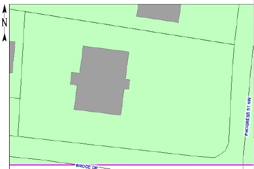
300 Broce Drive, Blacksburg VA 24060: |
The orientation of 300 Broce Drive is parallel to Broce Drive and Progress Street, about 8° west from the north-south direction. This is sufficiently close to a south orientation facing Broce Drive for placing the solar collectors on the south side. |
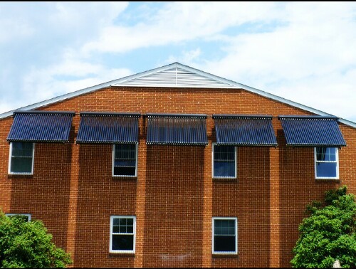
View from Broce Drive (south side): 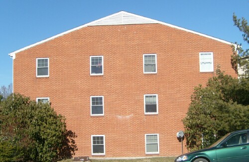 |
| The tree barely shown on the extreme right in the picture above and on the left in the picture below was removed in order that it not shade the solar collectors during early mornings. At least three trees will be planted on the north side of the property to replace it. |
View from Progress Street (east side): 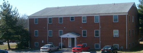 |
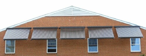
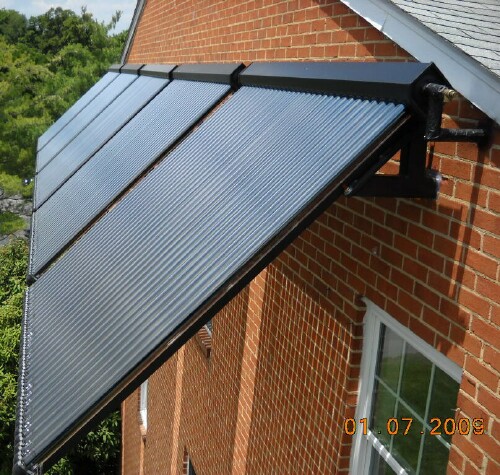
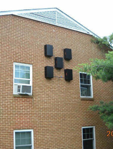
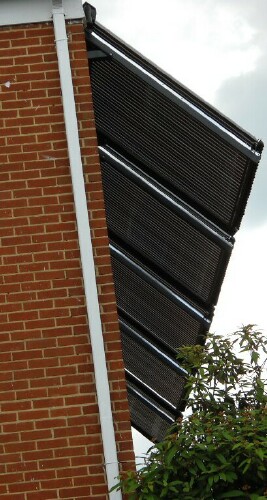
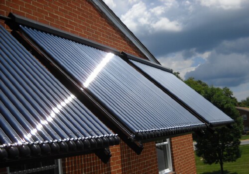
Five banks of thirty Apricus vacuum-tubes solar collectors for each bank: 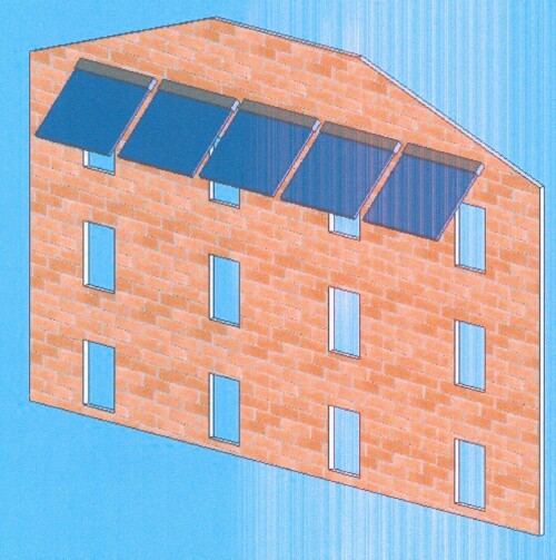
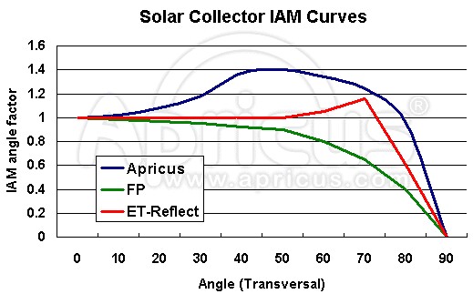
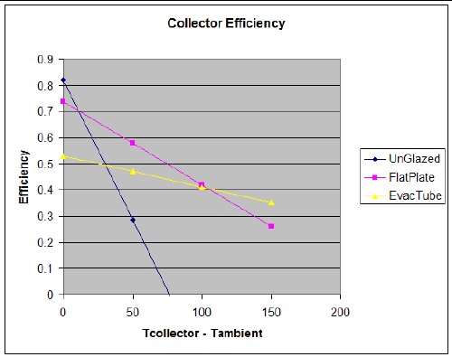
The hanging angle is 45°, which is about right for Blacksburg's latitude of of about 37° to favor winter sunlight. The best north-south orientation is with the collectors toward geographical south.(In Blacksburg VA magnetic north is about 6.5° west of geographic north, so magnetic south is about 6.5° east of geographic south. This is important to know when using a compass to find geographical south.) The orientation of the Broce-Drive side of the apartment house is about 8° toward the west from geographical south, which is adequate. It favors sunlight after noon. The Apricus vacuum-tubes solar collectors are tolerant of the incident angle deviating from 90°. Comparison of Incidence Angle Modifier (IAM) for solar collectors: Notice how the Apricus vacuum-tubes collector has a larger factor for off angles. |
 |
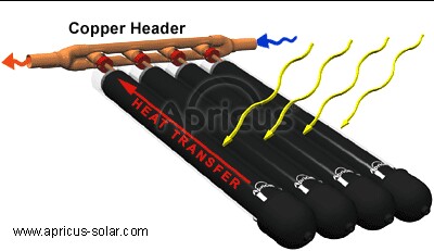
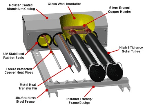
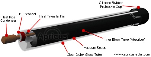
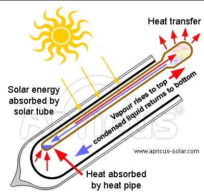
Vacuum-tubes solar collector: |
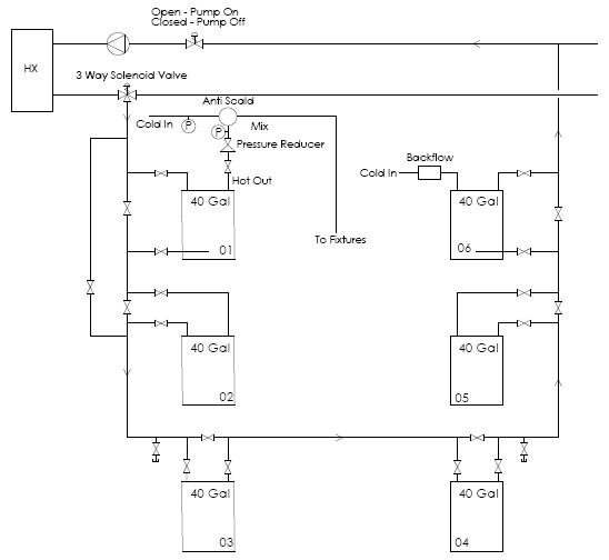
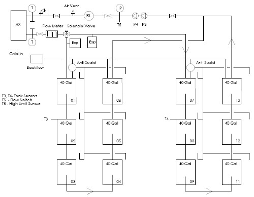
Note that the system is divided into two parts, one for the 6 south apartments and one for the 6 north apartments. They are separated by a hallway on three floors. The five 40-gallons and one 50-gallons hot-water heaters on each side serve as one 250-gallons hot-water tank for the SHW system. The heating elements for tanks 1, 2, 7 & 8 are set at 140°F; the heating elements for tanks 3 to 6 and tanks 9 to 12 are turned off. Thus tanks 1, 2, 7 & 8 do the heating needed when the solar collectors are not providing enough heat; the other 8 tanks provide hot-water storage. Five of the original hot-water heaters were installed in the 1970s, one in the 1980s, two in the 1990s and four in the 2000s. The 1970s and 1980s heaters were replaced with new ones during the installation of the SHW system. |
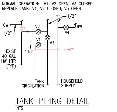
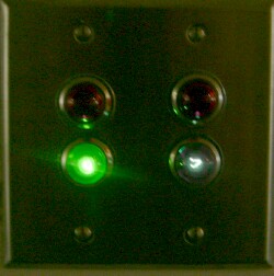
Controls: This valving allows the twelve original hot-water systems to function while the SHW system is installed. Then, only valves need to be turned on and off to place each apartment in the SHW system. Later, if a hot-water heater in an apartment fails, it can be isolated from the SHW system by merely turning on and off valves. |
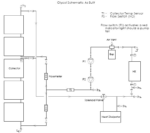
Note that the five banks of solar collectors are separated into a set of two banks and a set of three banks. This is keep the temperature in the manifold at the last bank in a set from getting too high. The propylene glycol flow from both sets are combined together to go into the heat exchanger for heating water. The heated water is then divided to flow into the two sets of six hot-water heater tanks. |
 |
Apricus AP-30 solar collector specifications:
Apricus Solar Collector General Specifications |
|
| Manifold Casing Material | Aluminum (grade 3A21) |
| Frame Material | 1.5mm 304 Stainless Steel |
| Header Pipe Material | 99.93% pure Copper & lead free 45% silver brazing |
| Insulation | Compressed Glass Wool; K = 0.043W/mK |
| Rubber Seals and Rings | HTV grade silicone rubber |
| Optimal installation angle | 20-70o Vertical, -5o to +5o Horizontal |
| Maximum Operating Pressure | 8 bar - 116 psi |
| Optimal flow rate | 0.1 L/min/tube - 0.026 G/min/tube |
| Performance Data ( SPF) | Conversion Factor: h0 = 0.717 Loss Coefficients: a1 = 1.52, a2 = 0.0085 |
Length (nominal) |
1500mm (1800mm) |
Outer tube diameter |
58 mm |
Inner tube diameter |
47 mm |
Glass thickness |
1.6 m |
Thermal expansion |
3.3x10⁻⁶ oC |
Material |
Borosilicate Glass 3.3 |
Absorptive Coating |
Graded Al-N/Al |
Absorptance |
>92% (AM1.5) |
Emittance |
<8% (80oC) |
Vacuum |
P<5x10⁻³ Pa |
Stagnation Temperature |
>200oC |
Heat Loss |
<0.8W/( m2 oC ) |
Maximum Strength |
0.8MPa |
Model Specifications |
|
Model |
AP-30 |
| Overall Length (mm / inch) | 1980 / 77.9 |
| Overall Width (mm / inch) | 2196 / 86.4 |
| Overall Height (mm / inch) | 156 / 6.1 (including flush roof mounting frame) |
| Absorber Area (m2 / ft2) 2 | 2.4 / 25.8 |
| Fluid Capacity (ml / ounces) | 833 / 28.2 |
| Gross Area (m2 / ft2) 3 | 4.35 / 46.8 |
Dry Weight (kg / pounds) |
95 / 209 |
The system for 300 Broce Drive is designed to deliver approximately 90% of the hot water in the summer and about 50% of the hot water in the winter.
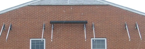
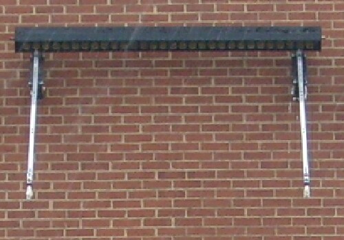
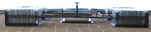
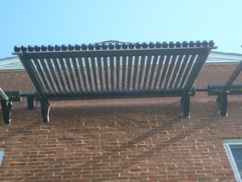
One heat dissipater for each 30 vacuum-tube solar collectors is mounted on the north side of the building:
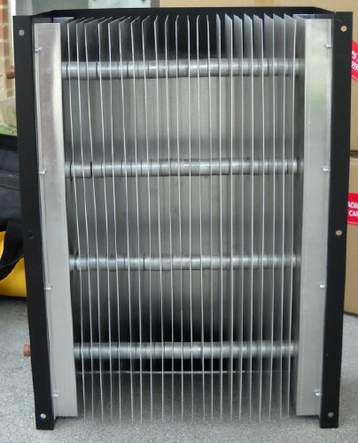 |
Layout of the five heat dissipaters: 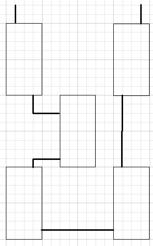 |
 |
 |
Boxes of collector tubes and tubes manifolds: 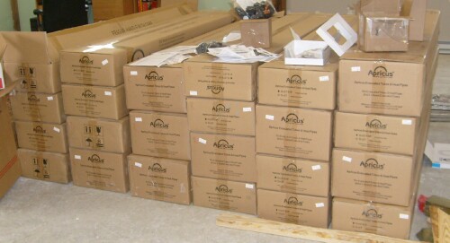 |
Tubes manifold: 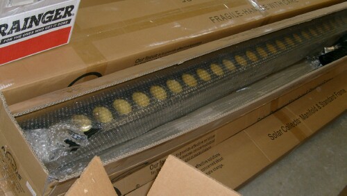 |
Collector tube: 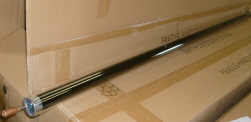 |
Upper end of collector tube:
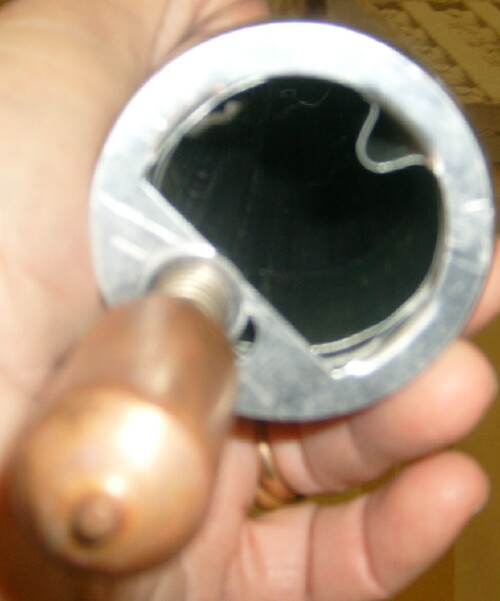 |
Tubes bracket with manifold at top: 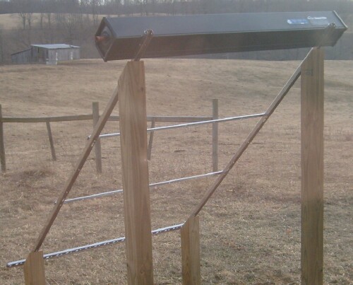 |
RPZ (Reduced Pressure Zone) valve and sump-pump arrangement: 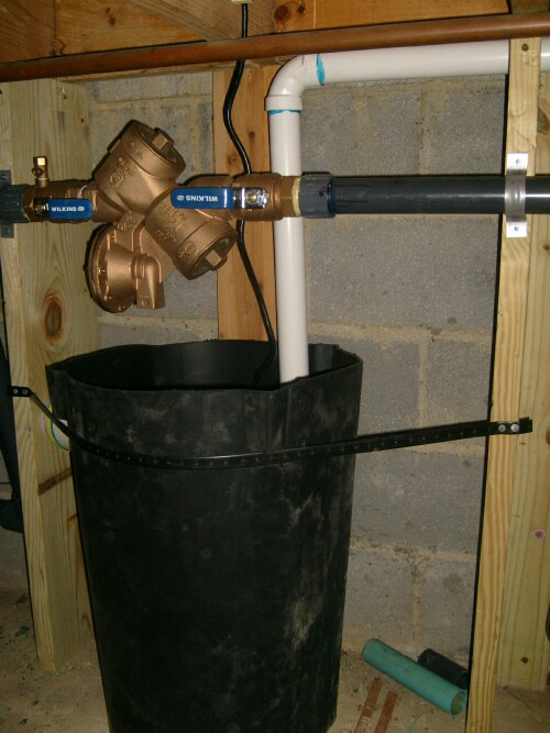 The white pipe from the sump pump in the tub runs into the edge of one apartment and then outside the building. |
Hall monitor, one for propylene-glycol flow and one for water flow: |
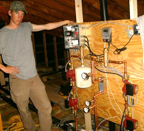
Control board and 3 pressure-relief tanks; left one for propylene glycol and the two identical large ones in the rear for the two sets of 6 apartments: 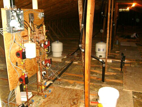 |
Installed two flow meters to measure hot-water usage: 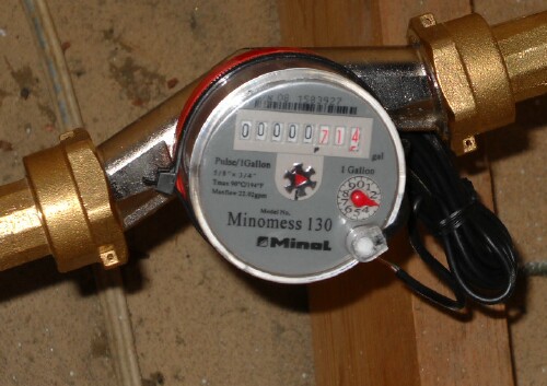 |
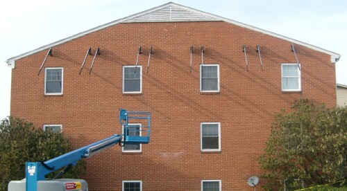
10 solar-collectors' brackets and one of the 5 solar-collectors-pipes' manifolds: 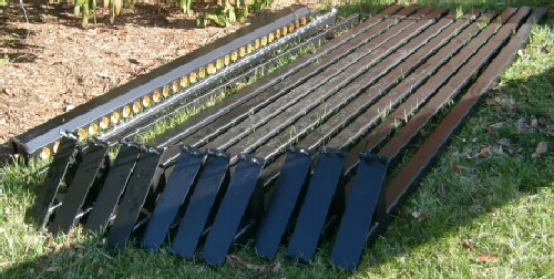 |
Chris Roberts, Pat Bixler & Devan Bixler (inside) inserting the first bracket: 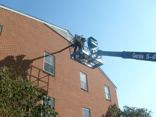 |
First bracket inserted: 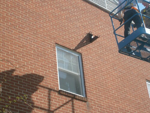 |
The 10 brackets inserted: 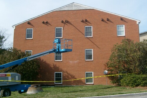 |
Pat Bixler installing brackets: 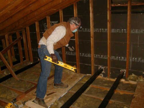
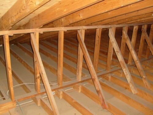
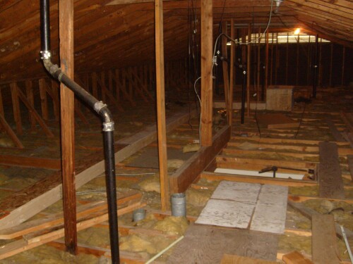
The 1968 insulation batts in the attic floor, shown here, will be removed and 5" of open-cell foam will be blown between the joists. The old attic fans in the four top-floor apartments will be replaced by new attic fans with thick-insulated doors on top of them that automatically open when the fans are turned on. The control board will have an insulated shed built around it open to the ceiling of the apartment underneath to keep it warm. The insulated water pipes in the attic will be surrounded by an insulated chase open to the ceiling below to keep them warm. There will be a federal tax deduction for the insulation as well as the solar-hot-water system. |
Solar-collectors' brackets in place: 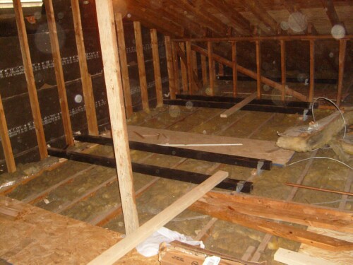 |
Brackets' extenders in place:
 |
Chris Roberts installing manifolds: 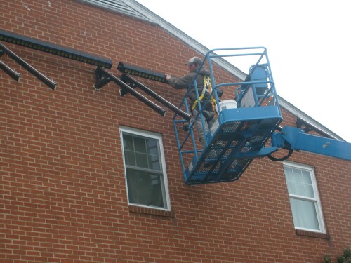 |
All manifolds installed: 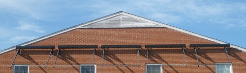 |
First solar-collector tube installed by Chris Roberts: 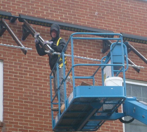 |
First bank of 30 collector tubes installed: 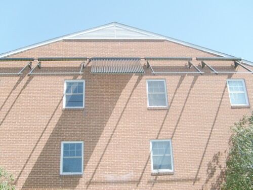 |
 |
Chris Roberts welding bottom support to prevent sagging: 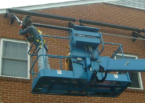 |
 |
 |
|
 |
Chris Roberts, master craftsman, after a job well done!: 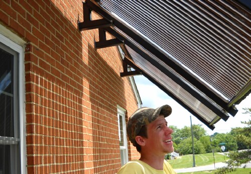 |
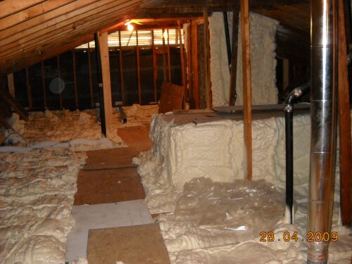
Insulated boxes around water containers and pipes: 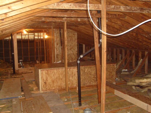 |
 |
Closed-cell foam was blown in between the joists: 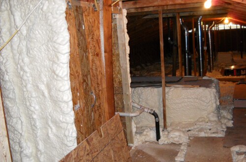 Also shown are the vent pipes through the roof from the kitchens that were installed. |
 |
The old attic fans were replaced by insulated ones: 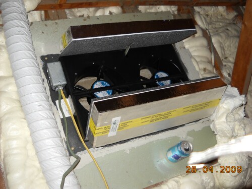 The insulated cover opens when the fan is turned on. |
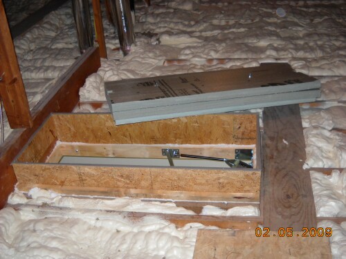
New attic stairs with insulated cover: 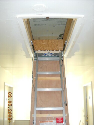 |
 |
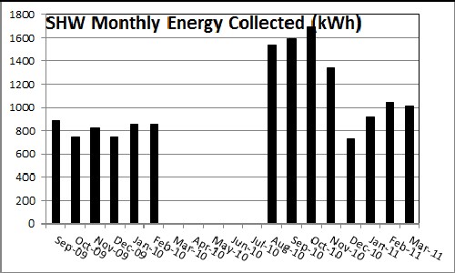
The accuracy of the first 6 months' data is uncertain. No instrument measured solar-energy collected during the months Mar-Jul 2010.
Apricus has informed me that the carbon payback for the collectors is about 90 days of good output.
A tax deduction of up to $1.80 per square foot is available to owners or designers of new or existing commercial buildings that save at least 50% of the heating and cooling energy of a building that meets ASHRAE Standard 90.1-2001. Partial deductions of up to $0.60 per square foot can be taken for measures affecting any one of three building systems: the building envelope, lighting, or heating and cooling systems. These tax deductions are available for systems “placed in service” from January 1, 2006 through December 31, 2013.
The system was completed on 1 July 2009. Data are not available for the electrical usage of the apartments for the 1 July 2008 to 31 December 2008 period, so the period 1 July 2007 to 31 December 2007 will be used to compare to the data for 1 July 2009 to 31 December 2009 for calculating the tax deduction. The area of the 12 apartments and the hallways is 10,843 ft^2 (72'2" x 50'1"). Thus, the deduction for saving greater than 50% of the heating and cooling energy would be $19,577; the deduction for saving less than 50% of the heating and cooling energy would be $6,506.
L. David Roper, http://www.roperld.com/personal/roperldavid.htm; roperld@vt.edu
06-Apr-2016