L. David Roper
http://www.roperld.com/personal/roperldavid.htm
4 April, 2016
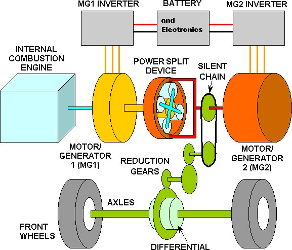
"Power-split hybrid or series-parallel hybrid are parallel hybrids. They incorporate power-split devices allowing for power paths from the engine to the wheels that can be either mechanical or electrical. The main principle behind this system is the decoupling of the power supplied by the engine (or other primary source) from the power demanded by the driver.
A combustion engine's torque output is minimal at lower RPMs and, in a conventional vehicle, a larger engine is necessary for acceptable acceleration from standstill. The larger engine, however, has more power than needed for steady speed cruising. An electric motor, on the other hand, exhibits maximum torque at standstill and is well-suited to complement the engine's torque deficiency at low RPMs. In a power-split hybrid, a smaller, less flexible, and highly efficient engine can be used. The conventional Otto cycle (higher power density, more low-rpm torque, lower fuel efficiency) is often also modified to a Miller cycle or Atkinson cycle (lower power density, less low-rpm torque, higher fuel efficiency). The smaller engine, using a more efficient cycle and often operating in the favorable region of the brake specific fuel consumption map, contributes significantly to the higher overall efficiency of the vehicle."
This is a rough diagram of the power-split device (planetary gear set or epicycle gears) for the Prius Hybrid Synergy Drive:
"Interesting variation of the simple design found, for example, in the well-known Toyota Prius are the: addition of a fixed gear second planetary gearset as used in the Lexus RX400h and Toyota Highlander Hybrid. This allows for a motor with less torque but higher power (and higher maximum rotary speed), i.e. higher power density."
This is a rough diagram of the double planetary gear set of the HiHy:
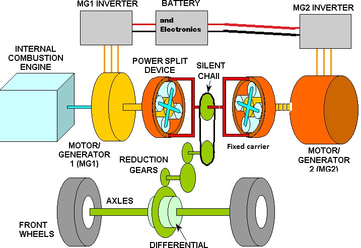
Not shown is a "counter" gear between the two ring gears.

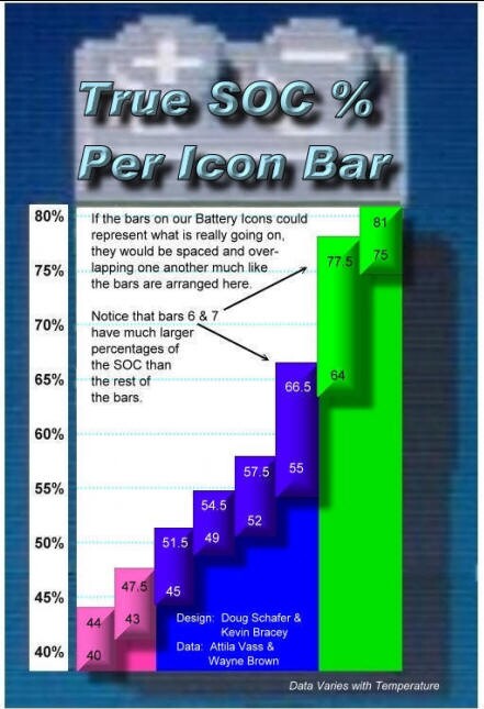
Note that the minimum SOC is 40% and the maximum SOC is 80% to make the battery have a longer lifetime. I have never seen 8 bars or 1 bar in the six years and 100,000 miles of driving the HiHy; several other HiHy drivers report the same.
NiMH-battery discharge curves:
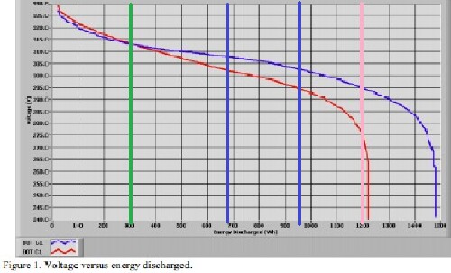
BOT (blue curve)= Before Test; EOT (red curve) = End Of Test
The vertical green line is the approximate maximum SOC for the green bars on the SOC display; the vertical pink line is the approximate minimum SOC for the pink bars on the SOC display; the two vertical blue lines are the approximate maximum and minimum for the blue bars on the SOC display. The maximum voltage is ~313-volts at 80% SOC and the minimum voltage is ~295-volts at 20% SOC. The voltage boundaries for the blue bars are ~308-volts at ~65% SOC and ~303-volts at ~46% SOC.
Battery Display: The usable range of the NiMH battery is around 40-80% though it can, in extreme circumstances, briefly go 2-3% below or above those numbers respectively. The HV ECU is programmed to attempt to maintain a 60% SOC; that is approximately 6 blue bars on the energy display. If the display shows green 7 bars the charge is 70-80% SOC. If the display shows one pink bar the charge is 40-45%, but there is some hysteresis.
I thought about getting a Mitsubishi Outlander Plug-In Hybrid, but decided to upgrade our 2006 HiHy to a plug-in instead.
| Battery Energy | Battery Weight | Charge Time | Range | Top Electric Speed |
|---|---|---|---|---|
~7.2 kWh |
~198 lbs |
~5.5 hours |
~20 miles |
52 mph |
DIY Price |
RTI Price |
Install Price |
Shipping |
Installer Travel |
$6579 |
$8500 |
$750 |
$450 |
$500 |
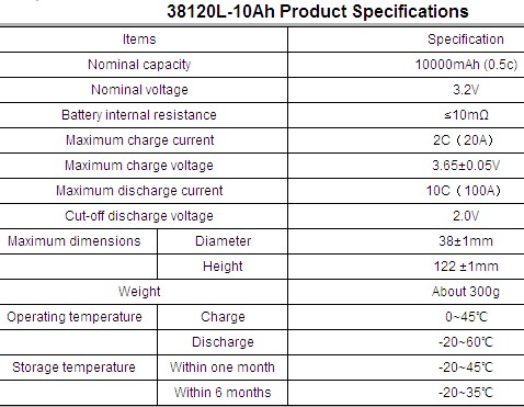
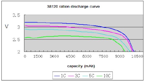
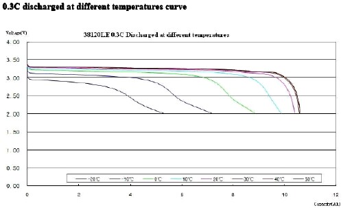
Lithium-ion with LiFePO4 cathode and graphite anode; 216 HeadWay 38120S 10-Ah capacity at 1C, continuous current of 10C, ~3.2-volts cells in parallel pairs in the battery pack for ~346 volts and ~7.2-kWh energy stored. (See graphs below.) Made by http://www.headway-cn.com. (A continuous current of 10C means that 100 amperes will discharge a 10-Ah battery in one hour.) Cell specifications and download a pdf and another.

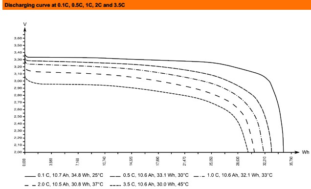
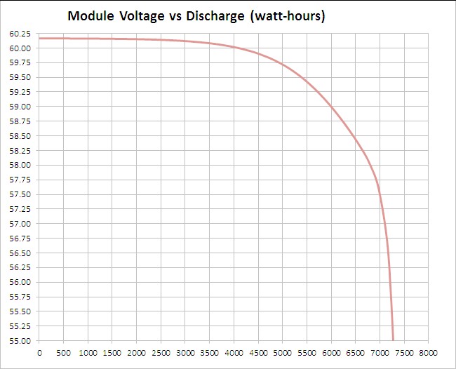
Plot of the HiHy NiMH-battery discharge curve, adjusted for 96,000 miles, along with the LiFePO4-battery discharge curves for 0C (brown curve for zero current extrapolated from higher C curves), 0.1C, 0.5C, 1C, 2C and 3.5C currents:
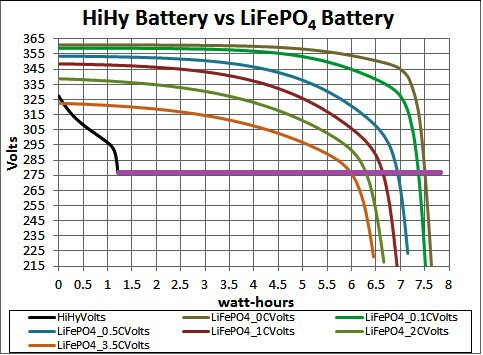
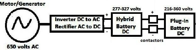
The plug-in battery (PIB) is connected in parallel to the hybrid battery (HB) by two contactors, one for the negative wire and one for the positive wire. Two contactors are for redundancy to make sure that the HB is never overcharged by the PIB: When the HB is above a certain voltage, perhaps ~315-volts, less than its maximum voltage, ~325-volts, the contactors are open, so that current cannot exist from a highly-charged ~350-volts PIB into the HB. The result is that the HB is always nearly full after a full charging of the PIB until the PIB voltage gets below the contactors' cutoff voltage.
The PIB voltage never goes below the HB minimum voltage, ~275-volts, shown as a purple horizontal line in the graph above.
I assume that the DC voltage imposed on the batteries during regeneration is somewhat less than the highest voltage for the HB, perhaps ~315-volts, to keep it from being overcharged. When both batteries are at the minimum voltage, ~275-volts, then both batteries would be charged by regeneration up to the contactor cutoff, ~315-volts. This can happen at a long distance from the last charging of the PIB and when going down a long hill after going up it. As can be seen in the graph above, this does not charge the PIB anywhere near full (brown curve on the right and top).
Interesting web page about lithium-ion batteries: http://rgp.calpoly.edu/documents/The_Inside_Story_of_the_Lithium_Ion_Battery_0511.pdf
C rates: "The C-rate signifies a discharge rate relative to the capacity of a battery in one hour. A rate of 1C would mean an entire 1.6Ah battery would be discharged in 1 hour at a discharge current of 1.6A. A 2C rate would mean a discharge current of 3.2A." (Also see: http://web.mit.edu/evt/summary_battery_specifications.pdf .)
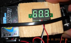
It is easy to measure the voltage of one of the six modules, which gives a rough measure of the SOC:
Installation can be done anywhere in the world, including at the home location of the vehicle. There is a Do-It-Yourself option to reduce cost.
The following are various models for calculating the increase in mpg by charging the PIB every day.
The EPA testing of the 2006 standard V6 Highlander and the 2006 HiHy show an increase of ~6 mpg for the HiHy due to regeneration and engine stop-start. The hybrid battery is 1.46-kWh. So, one might surmise that the extra ~7.2-kWh battery should add ~6x5/1.46 = ~28 mpg due to regeneration. Adding this to the current ~24.5 mpg, the new mpg should be ~53mpg. (Adding another ~7.2-kWh battery pack would bring that up to ~81 mpg.) However, from the graph above one can see that only a small part of the ~7.2-kWh can be filled by regeneration when the plug-in battery's voltage is lower than the voltage of the hybrid battery. This only considers the extra mpg due to regeneration and does not consider the extra mpg if the plug-in ~7.2-kWh battery is charged regularly. I plan to charge it every evening.
However, the Plug-In system for the Prius increased the mpg by ~27% for an empty battery. For the HiHy that would correspond to ~31 mpg. However, the Hymotion plug-in system battery does not participate in regeneration.
My experience with the Hymotion plug-in system for the 2005 Prius was an increase in mpg of about 30% average year round. For the HiHy that would correspond to ~32 mpg.
Since a gallon of gasoline has the potential of creating 34 kWh, electric motors are ~90% efficient and gasoline engines are ~25% efficient, the ~7.2-kWh pack fully charged will take the HiHy ~18 miles. However, regeneration will extend that range to perhaps ~20 miles. The Roper HiHy averages ~40 miles/day including long 300-400-miles trips about once a month; so, usual daily trips are ~25 miles or less.
This HiHy was driven 100,000 in 6 years, or 16,667 miles/year. If the PI system reduces usage by 10 mpg (from ~25 mpg to ~35 mpg), the saved number of gallons/year is 190.5. At ~$3.50/gallon, the save money per year is ~$667 the first year. If the price of gasoline increased 5%/year, the payback period for the PI system would be ~10 years.
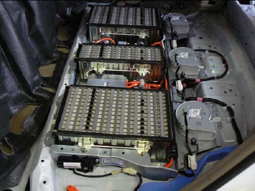
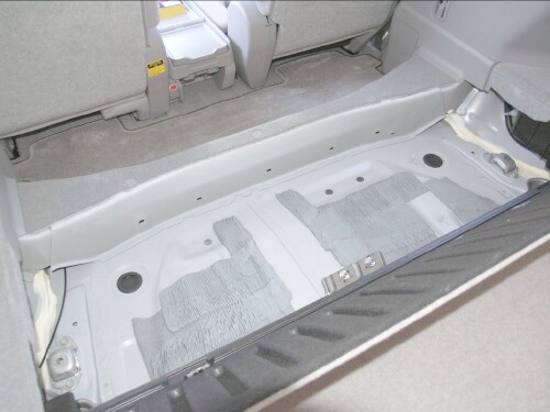
The ~7.2-kWh battery pack (six modules of dimensions 29” x 6 3/8” x 3 5/8”, 33 lbs) is in the well into where the 3rd-row seat was folded:
| Rear-seat well after 3rd-row seat is removed. | Rear-seat well after 3rd-row seat is removed. |
|---|---|
 Front view: partial cover of well is down. |
|
One of the three battery pack modules in the bottom row of the pack is in front of the divider near the front of the well and the other two are behind the divider. The other three module are stacked on top. The well with the three partial battery packs is protected by a 3/8" plywood cover at the back and 3/4" plywood in the front.
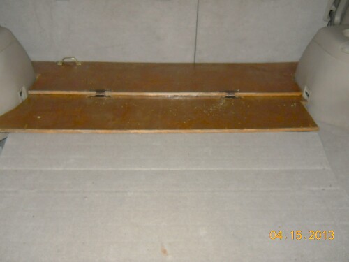
The cover for the battery well consists of two 3/8" overlapping pieces of plywood:
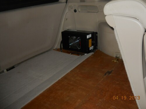
The 120-volts ElCon PFC-2500 charger (13.9" x 7.7" x 5.5", 15.4-lbs) starts out at ~12.7-amps (or ~15.2-kW). Near the end of charging it reduces the current at a fixed voltage. Finally, it equalizes the 108-batteries-pairs voltages.
http://www.elconchargers.com/catalog/item/7344653/7638094.htm
The charger is on a 1/4" plywood board attached by bolts to the left-back tray:
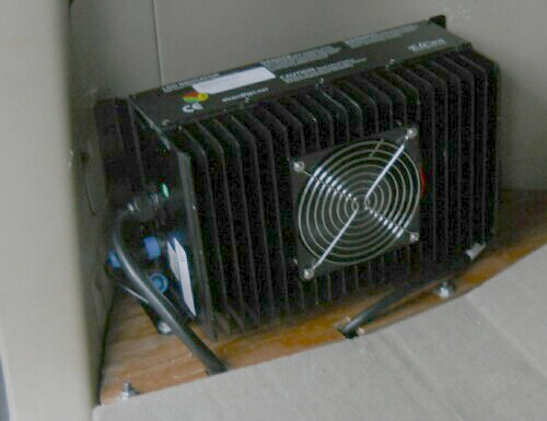
Note that the access to the back-left lights is blocked. Since they are LED the access should not be needed often.
Here are the two possible ways to mount the charger:

I think the orientation on the left is turned upside down; the mounting bracket should be on the bottom as in the picture above. I like the corrected left orientation better because the right orientation would collect debris between the fins.
I constructed a cover of cardboard for the charger to protect it from large dogs and cargo:
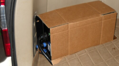
Of course, it must be removed when the charger is charging the battery pack.
A block of wood is behind it to hold it snugly in place. This cardboard cover may be replaced by a plywood cover, if cardboard does not work.
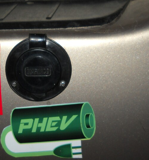
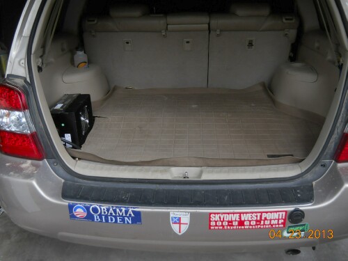
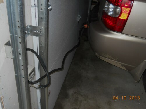
Here is a picture of the plug on the right of the back bumper for charging the plug-in battery using 120-volts house current:
Remove the lid on the rear controller and install jumpers J14 and J15 at the top center. Then plug in the car and see if the charger turns on. If it does not, unplug the car and cycle the ignition on off, then plug it in again and see if it charges.
If it does charge, then let it charge for 30 min, then remove jumpers J14 and J15 and let it continue charging until it stops.
Installing the jumpers allows the charger to revive a over depleted pack. The pack can be over depleted by repeatedly turning it on when it is empty. Each time the voltage drops a bit until it will no longer turn on.
Do not allow the charger to do a complete charge cycle with J14 & J15 installed (covering 2 pins) because in this state the battery-management system is bypassed and not working and there is nothing to prevent over charging the pack.
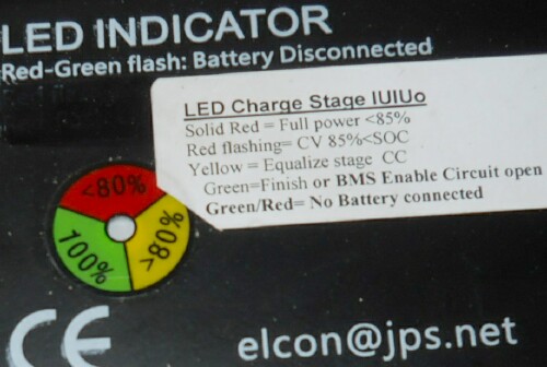
The green light on the rear board marked "D6 CELL LOOP OK" should be on at all times. If it is out the pack is over depleted or something is broken.
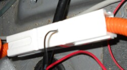
I got wired jumpers and soldered them to switches to make it easier to do this jumpers procedure:
The two switches are velcroed together and are in the right-rear tray to make them easy to actuate.
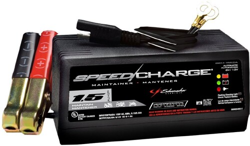
There is a 12-volts trickle charger connected to the auxiliary 12-volts battery which trickle charges that battery when the plug-in battery is being charged. It is located behind the battery pack and wired to the front-seat electric module hot wire nearby. Bought Schumacher 1.5-amps trickle charger (Model: SEM-1562A) from Advance Auto.
There are 12-volts hot wires at the right rear of the HiHy at the electric-seat controller into which to wire the trickle charger.
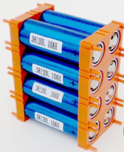
This is the box in which the battery modules arrived:

It rested on a wood base; the total weight was 242-lbs.
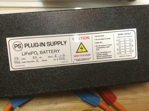
There are six battery modules with 18 pairs of 10-Ah LiFePO4 batteries (Headway HW-38120S) in each module, for a total of 108 pairs or 216 batteries. Each module has ~58-volts and 20-Ah, so the total voltage for all six modules in series is ~348 volts. Therefore, the maximum energy stored is ~7.2 kWh. Each battery module weighs 33 lbs, with a total battery-pack weight of 198 lbs.
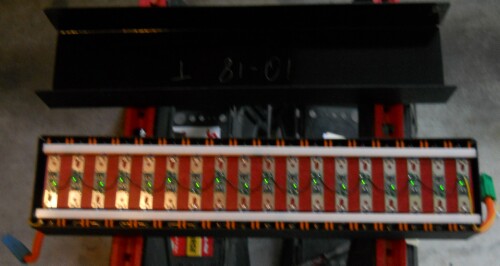
Here is what a battery module looks like before the ABS case is installed around it:
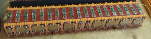
This module has 19 battery pairs for a Prius; a HiHy module has only 18 battery pairs.
The modules are enclosed in an ABS plastic case:
The six modules are placed in two layers of three modules in the 3rd-row seat's well. The pack is secured to the vehicle by four straps attached to the 2nd-row seat base in front and by Velcro between the bottom front battery and the rug below it and between the modules::
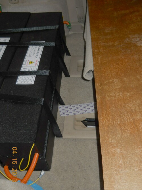

Notice the short Velcro strip at the back of the top layer of module to help hold the plywood cover in place. Note the red 100-lbs strap horizontally around the top layer of modules.
The two black straps are rated for 200-lbs each and the crossed red straps is..are rated for 300-lbs each. The black straps are anchored to the 2nd-row seat two center brackets in the front and riveted hooks in the back. The red strap is anchored to 2nd-row seat outer brackets in the front and riveted hooks in the back.
The modules in the top layer are connected by Velcro to the modules in the bottom layer:
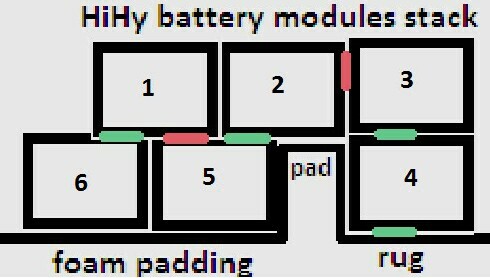
The 2" Velcro strips holding the modules together are indicated in green; the red ones are ones that should have been placed. The floor in the back is uneven, so foam padding was used to even it out. The pillar top is slightly below the top of the bottom row of modules, so foam padding was put there to even out the heights. A 100-lbs strap was installed horizontally around the top layer.
The batteries are covered with 3/8" plywood:
A 2" Velcro strip is between the back of the board and the battery pack. Two latches to attach to the square loops on the wheel wells, not shown here, are screwed to the board. The top board is hinged to the bottom board so that it can be lifted up to allow more leeway for folding the seat forward.
A Weathertech cargo liner is on top of the cargo area for protection from liquid spills and mud.
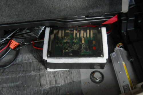
There are two control boards, one in the back and one in the front:
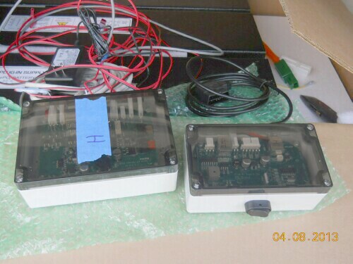
Note the on/off switch on the side of the front module on the right.
The front control board is in the open space under the center console between the front seats:
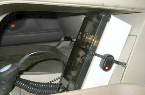
The red light shows that the plug-in system is on.
Its OBDII cable is run under the dash to plug into the OBDII receptacle very near the foot-actuated emergency brake. In fact, a foot can easily unplug the OBDII cable, so two plastic ties hold the cable onto the receptacle:
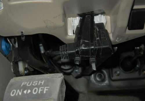
The emergency brake is at the bottom left.
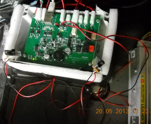
The back control-board module is to the right behind the batteries and in front of the tool tray:
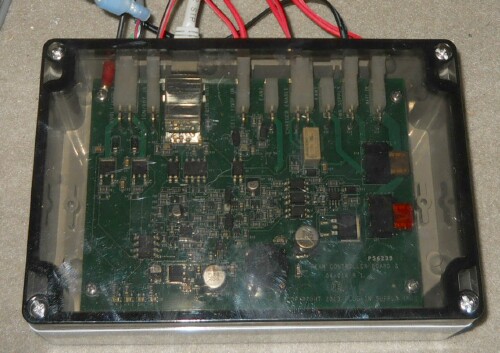
It has a small green light near top center that shows that the plug-in system is working. There are two jumper location near the top center, J14 & J15 that sometimes have to be closed to get the charger to work.
The back module can be pulled back into the space of the tool tray after the tray is removed in order to observe its indicator lights and manipulate the jumpers:
Here is a picture of the contactors module:
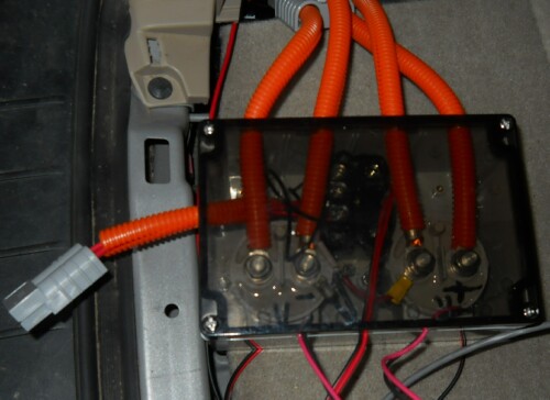
One of the contactors is in the positive line and the other is in the negative line, to give redundancy. They are set to open at a voltage less than the maximum voltage of the hybrid battery to prevent overcharging the hybrid battery.
 |
|---|
 |
 |
 bumper stickers from Zazzle.
 They fit ok under the Plexiglas cover. I ran the wires into the right-hand tray to make the switches easy to actuate.
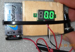
 bumper stickers from Zazzle.
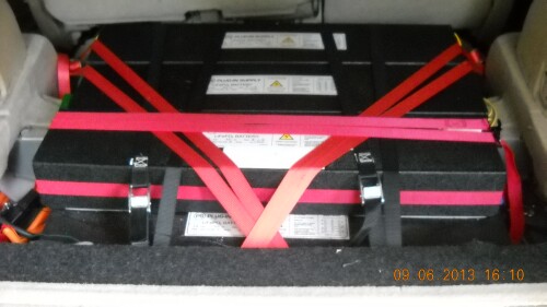
 Here is a closeup of 4 of the battery pairs and the BMS boards that contect the pairs.
 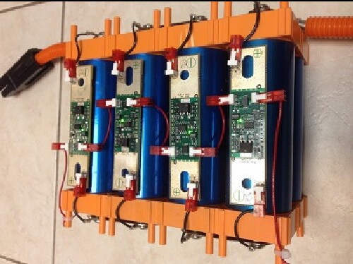 Left the cable from the hybrid battery in place to use it for connecting a future kit for house backup when the grid is down. Placed an ad on EVAlbum for the charger and 6 modules.
HiHy Plug-In Data |
kWh/Gal: |
33.4 |
HiHy eff. |
35% |
Mot. eff.: |
95% |
Charger Efficiency: |
92% |
No PI mpg: |
24.5 |
Gas cost: |
$3.50 |
Electric Cost: |
$0.11 |
date |
miles |
mpg |
Gas Gal. |
kWhPI |
kWhPICor |
Charging |
kWhEqTotal |
GalEqTotal |
mi/kWhEq |
mi/GalEq |
Cost |
Trips |
Temp/Sun |
|
6-May-13 |
26.2 |
33.6 |
0.78 |
6.97 |
6.41 |
OK |
33.01 |
0.99 |
0.79 |
26.5 |
$3.50 |
PP,CC |
cloudy |
54/10 |
7-May-13 |
26.3 |
35.3 |
0.75 |
7.38 |
6.79 |
OK |
32.26 |
0.97 |
0.82 |
27.2 |
$3.42 |
CN,CC/PP |
rainy |
59/8 |
8-May-13 |
35.4 |
29.9 |
1.18 |
10.09 |
9.28 |
1 |
49.63 |
1.49 |
0.71 |
23.8 |
$5.25 |
Lo,PP |
rainy |
57/8 |
9-May-13 |
78.7 |
32.3 |
2.44 |
10.05 |
9.25 |
2 |
91.43 |
2.74 |
0.86 |
28.7 |
$9.63 |
PD,local |
sun,rain |
74/3 |
10-May-13 |
51.2 |
35.7 |
1.43 |
10.77 |
9.91 |
3 |
58.67 |
1.76 |
0.87 |
29.1 |
$6.20 |
La,local,PP |
sun,rain |
77/4 |
11-May-13 |
26.7 |
31.4 |
0.85 |
5.42 |
4.99 |
4 |
33.82 |
1.01 |
0.79 |
26.4 |
$3.57 |
CC,PP |
rainy |
71/7 |
12-May-13 |
33.9 |
28.6 |
1.19 |
8.14 |
7.49 |
5 |
47.73 |
1.43 |
0.71 |
23.7 |
$5.04 |
CC,Lo,PP |
sunny |
57/2 |
13-May-13 |
25.0 |
30.5 |
0.82 |
7.38 |
6.79 |
OK |
34.76 |
1.04 |
0.72 |
24.0 |
$3.68 |
PP,CC |
sunny |
56/3 |
14-May-13 |
26.1 |
32.8 |
0.80 |
7.53 |
6.93 |
OK |
34.11 |
1.02 |
0.77 |
25.6 |
$3.61 |
PP,BL |
sunny |
70/2 |
15-May-13 |
22.3 |
36.5 |
0.61 |
6.49 |
5.97 |
OK |
26.90 |
0.81 |
0.83 |
27.7 |
$2.85 |
CN,PP |
sunny |
85/1 |
16-May-13 |
121.7 |
29.0 |
4.20 |
8.11 |
7.46 |
OK |
148.27 |
4.44 |
0.82 |
27.4 |
$15.58 |
local,R |
sunny |
78/2 |
Average: |
43.0 |
32.3 |
1.37 |
8.03 |
7.39 |
53.69 |
1.61 |
0.79 |
26.4 |
Many short trips were made with charging every time the HiHy was in the garage; that is, once or twice a day.
774 miles traveled in 13 days for 59.5 miles per day. Electricity used was 80-kWh. MPG was 34.2.
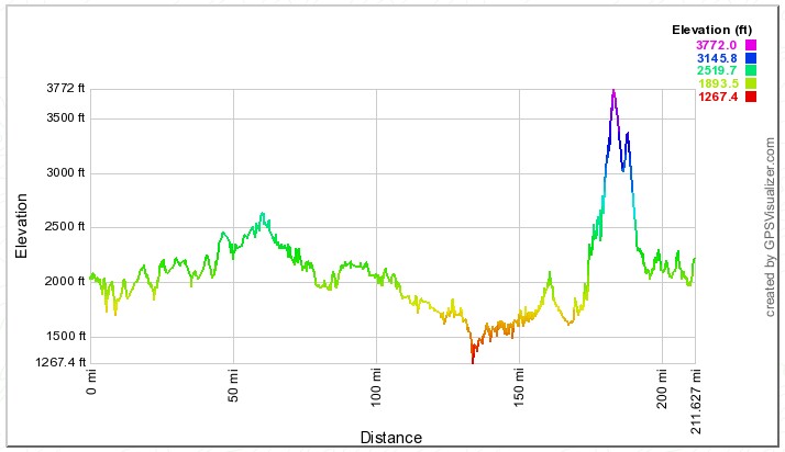
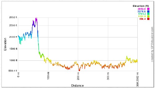
Kept PI on both ways. Fully charged before leaving and before returning. Opportunity charged several times while there.
Elevation changes going:
kWh/Gal: |
33.4 |
HiHy eff. |
35% |
Mot. eff.: |
95% |
Charger Efficiency: |
92% |
No PI mpg: |
24.5 |
Gas cost: |
$3.50 |
Electric Cost: | $0.11 | |
date |
miles |
mpg |
Gas Gal. |
kWhPI |
kWhPICor |
Charging |
kWhEqTotal |
GalEqTotal |
mi/kWhEq |
mi/GalEq |
Cost |
|||
17-May-13 |
390.0 |
26.7 |
14.61 |
8.35 |
7.68 |
1 |
496.22 |
14.86 |
0.79 |
26.3 |
$52.04 |
|||
18-May-13 |
37.0 |
28.4 |
1.30 |
15.12 |
13.91 |
OK |
58.63 |
1.76 |
0.63 |
21.1 |
$6.22 |
|||
20-May-13 |
390.6 |
26.8 |
14.57 |
8.26 |
7.60 |
2 |
495.05 |
14.82 |
0.79 |
26.4 |
$51.92 |
|||
| The 18 May entry is for 2 days, including 19-May; the PIB was charged 4 times during those 2 days (2.34, 6.41, 2.20 & 4.17 kWh). | ||||||||||||||
| 1: Had to use jumpers/ignition procedure to get charger to start charging | ||||||||||||||
| 2 : Charged ok to 2.61-kWh and then stopped; had to use jumpers/ignition procedure to get charger to start charging again | ||||||||||||||
Consumption and regeneration with plug-in on and plug-in battery depleted for last 25-30 miles for trip home: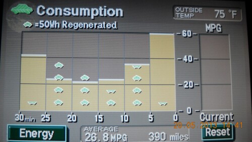
Each green car represents 50-Wh regeneration of electricity.
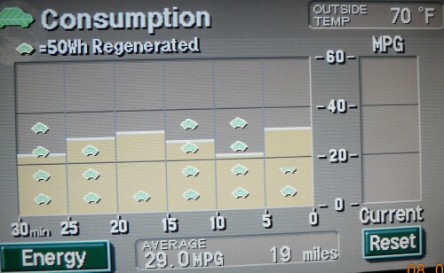
Same trip as above with plug-in off:
A typical Energy display with plug-in on and plug-in battery not depleted:
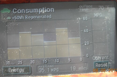
It appears that the PIB is receiving all the regeneration because no regeneration is shown for the HB.
ConVerdant Vehicles makes "Plug-Out Kits" for hybrid and plug-in vehicles to provide power to a few electric appliances in a house during a power outage. Plans are to connect the 3-kW 120-volts Plug-Out Island-kit cable to the HiHy when the plug-in is installed. The kit has a similar cable that can be easily plugged into the cable coming from the HiHy battery to the plug-in battery. The plug-in battery will not be involved.
As for the usual operation of the HiHy, the gasoline engine will run only when needed to charge the HiHy battery; that is, the HiHy serves as a very efficient, quiet and low-polluting generator for house emergencies. The Plug-Out weighs 62 pounds, so is easy to move around; it could be put on wheels. The tailpipe could be connected to a pipe that goes outside the garage.
The 3-kW kit will be able to run the refrigerator (0.75 kW maximum), the 40" LCD TV (0.257 kW maximum), the microwave (1 kW maximum) and a 1-kW resistance heater. (We have a propane range and three wood fireplaces.) This can be done with an extension card and power strip or with a special switched circuit that contains only those four emergency appliances; the circuit would be switched from the grid to the kit in emergencies.
The 2-kW or 3-kW 120-volts kit could charge my Nissan LEAF at 120-volts and 12-amps. The 3-kW 240-volts kit or the 4-kW 240-volts kit could charge my Nissan LEAF at 240-volts and 16-amps. This might be useful during a power outage.